TekBox TBBT01 High-Current Bias-Tee
TekBox TBBT01 High-Current Bias-Tee
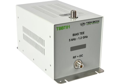
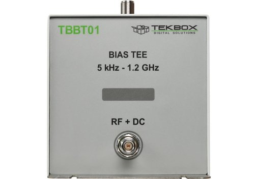
The TekBox TBBT01 bias-tee is used to measure the saturation effects of power inductors and bias voltage effects on capacitors. The majority of available bias-tees for power inductor testing operate at low frequencies, rendering them unsuitable for evaluating decoupling/bias inductors of RF power amplifiers or EMC filters. However, RF bias-tees usually have restricted current capabilities and cannot be employed in the lower frequency region. The TBBT01 can measure high bandwidth as well as high current. The TBBT01 can inject up to 10 ADC current into a 50-Ω RF-path and operates at frequencies between 5 kHz and 1.5 GHz. The TBBT01's insertion loss is unrelated to injection current.
High current bias tees can be used for a wide range of additional applications. Wherever inductors are used for decoupling and filtering in DC paths, it is best procedure to measure inductance under load current conditions. The same holds true for bias current-carrying pulse transformers.
- Usable frequency range 5 kHz...1.2 GHz.
- RF path insertion loss <1 dB typ. in the range 10 kHz...1 GH, <1.5 dB in the range 5 kHz...1.2 GHz.
- VSWR: 1 < VSWR < 2 in the range 5 kHz...1 GHz.
- Characterized frequency range 1 kHz...3 GHz.
- RF power handling 50 W from 5 kHz...1 GHz.
- RF connectors: N-female.
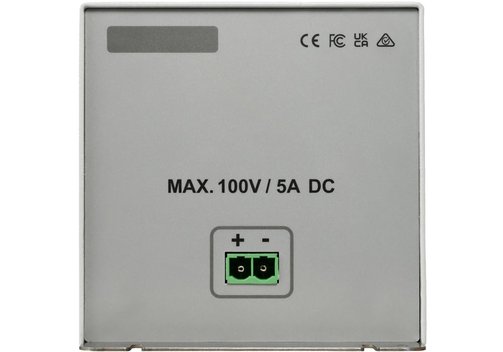
- Operating ranges voltage: max. ±100 V; current: ±5...±10 ADC, see datasheet/heat up characteristics plot, ±5 ADC continuous, max. ±15 ADC.
- DC path resistance <1.5 Ω at 22°C.
- DC input socket: Phoenix Contact 1998933, male; mating female terminal: Phoenix Contact 1967375.
- Dimensions (mm): 150 x 155 x 330; 3 kg.
Frequently Asked Questions:
Question: What is "Bias-Tee"?
Answer: "Tee" comes from a branching. The name is derived from the structure of the circuit as a tee, where the three connections are often arranged in the form of a "T". It is a network with three connections. The circuit is used to adjust the DC bias of electronic components. The combined terminal is connected to a component that receives both the bias voltage and high frequency. The LF (low frequency) connector is responsible for setting the bias voltage, while the RF (high frequency) connector is transparent to the high frequency signals but blocks the bias voltage levels.
Example: In order to ensure good reception of antennas in the most efficient and economical way, they are usually set up or mounted in exposed locations (e.g. on the roofs of buildings or cars). The power supply can then be provided by an interconnected bias tee (remote power supply).

Information on product safety:
Manufacturer:
TekBox Digital Solutions Vietnam Co. Ltd., Saigon Hi-Tech Park, Factory 4, 4F, Lot I-3B-1, N6 Street, Thu Duc City, 700 000 Ho Chi Minh City/VNM
www.tekbox.com
Responsible person:
Meilhaus Electronic GmbH, Am Sonnenlicht 2, 82239 Alling/DEU
info@meilhaus.com