TekBox TBCDNE-M2 and -M3 Coupling Decoupling Networks Emission
TekBox TBCDNE-M2 and -M3 Coupling Decoupling Networks Emission
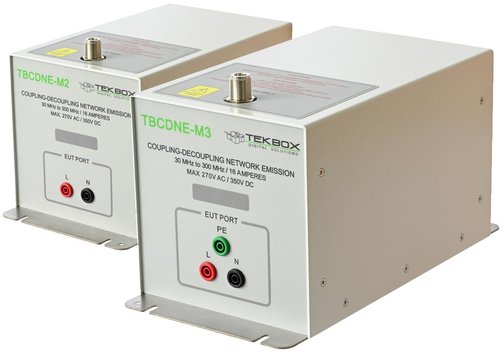
The TekBox TBCDNE series are a type of coupling decoupling networks used for an alternative technique of measuring radiated emission of lighting equipment in accordance with the CISPR 15 (EN55015) standard. It avoids the need for emission measurements on open area test sites (OATS). This method is defined in CISPR 15 edition 9 as an acceptable alternative to a traditional OATS test configuration with antennas and calibrated test sites. It is specified for a frequency range 30...300 MHz. The CDNE method and the associated limits up to 300 MHz can be only applied for EUTs (equipment under test) with clock frequencies below or equal to 30 MHz. In such a case, the product is deemed to comply with the requirements in the range 300...1000 MHz.
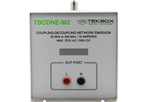
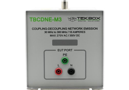
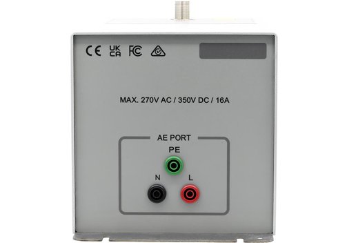
The Tekbox TBCDNE-M2 is designed for EUTs that do not have a PE (Earth) connection. The Tekbox TBCDNE-M3 is designed for measuring EUTs with PE, Neutral, and Line connections.
Comparing CDNs and CDNEs
The CDNEs are substantially more stringently specified, with reduced common mode (CM) impedance tolerance and additional parameters for CM phase tolerance and differential mode impedance equal to 100 Ω. A minimum 20 dB for longitudinal conversion loss shall prevent symmetrical voltage influencing measurement results.
CISPR 15 edition 9 also specifies that the mains supply cable of the EUT should be terminated with a CDNE positioned on the reference-ground plane for the OATS, SAC, or FAR measurement method.
Unlike CDNs, CDNEs are not appropriate for immunity measurements.
Model Overview
| Model | TBCDNE-M2 | TBCDNE-M3 |
| Application | Designed for EUTs that do not have a PE (Earth) connection | Designed for measuring EUTs with PE, Neutral, and Line connections |
| Compliance | CISPR 15 (IEC/EN 55015) Edition 9, CISPR 16-1-2, CISPR 16-2-1 | |
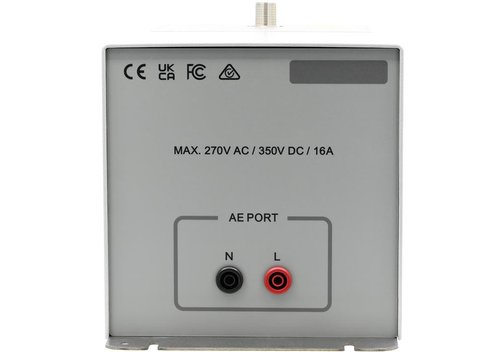
| Maximum supply voltage | 300 VAC, 600 VDC | |
| Maximum current | 16 A | |
| Frequency range | 30...300 MHz | |
| Common mode impedance | 150 Ω +10/–20 Ω (EUT port) | |
| Phase response | 0° ±25° (EUT port) | |
| Differential mode impedance | 100 Ω ±20 Ω (EUT port) | |
| Voltage division factor | 20 dB ±1.5 dB (EUT to RF output) | |
| Decoupling | AE to EUT decoupling: >30 dB; AE to RF output decoupling: >30 dB | |
| Connectors | RF output connector: N (female); EUT/AE connectors: 4 mm banana safety jacks, 4 mm slots in base plate for GND connection | |
| Dimensions (mm) | 300 x 150 x 150; approx. 2.5 kg; housing material: powder coated aluminium, stainless steel base plate | |
| Included | NIST traceable calibration data | |
| Optional accessories | Adaptor panel with shorting bar and N-connector; 50 Ω to 150 Ω adaptor panel for VDF measurement/calibration; OSL adaptors for common mode impedance measurement/calibration; Balun and OSL adaptors for differential mode impedance measurement/calibration | |

Information on product safety:
Manufacturer:
TekBox Digital Solutions Vietnam Co. Ltd., Saigon Hi-Tech Park, Factory 4, 4F, Lot I-3B-1, N6 Street, Thu Duc City, 700 000 Ho Chi Minh City/VNM
www.tekbox.com
Responsible person:
Meilhaus Electronic GmbH, Am Sonnenlicht 2, 82239 Alling/DEU
info@meilhaus.com
Customers also bought