Expansion Boards for HiL µLC Test System
Description
Files/Downloads
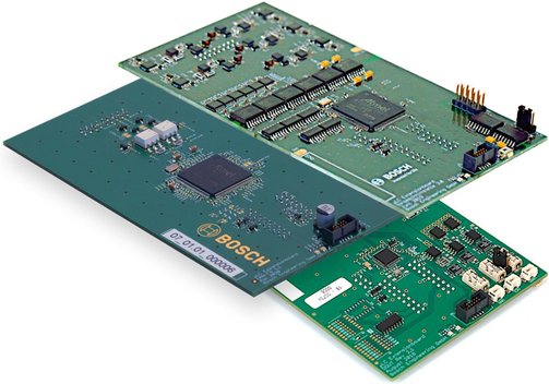
Additional Functions for the Hardware-in-the-Loop µLC Test System
With these expansion boards you can extend the functions of the hardware-in-the-loop µLC Test System without intervening in the software and without additional enabling mechanisms. The µLC Test System is available in different variants, i.e. individually or with an expansion card already installed. Only one expansion card can be installed in the µLC Test System at a time. An upgrading extension of the individual device or exchange for the bundled versions is possible, the device must be sent in for this.
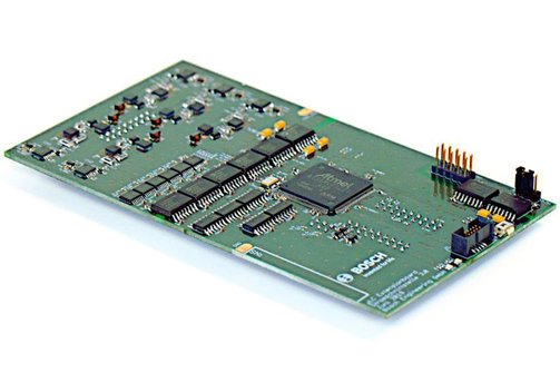
EB07 Expansion Board CAN-FD (F02U.005.545-01) for µLC Test System
- 2 independent channels, compatible with CAN and CAN-FD.
- Switchable termination resistor.
- CAN-FD data bit rates up to 5 Mbit/s.
- Adjustable bit rates and sample points with optional transmission delay compensation for high bit rates.
- Direct import of dbc and Fibex files.
- Short circuit proof.
EB01 Expansion Board Digital Outputs (F02U.004.880-01) for µLC Test System
- 14 additional digital outputs.
- Short circuit proof.
- Change to individual states possible: Low, High, High-Z.
- All outputs can be switched simultaneously.
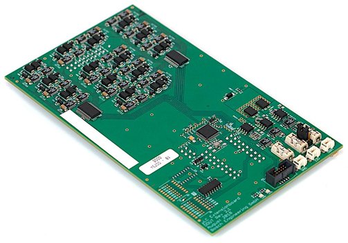
EB12 Expansion Board Current Loop Interface (F02U.004.844-01) for µLC Test System
- Five provided channels can be used to simulate up to five independent sensors.
- Integrated Lua scripting and API: Create automated tests.
- All common wheel speed sensors can be simulated.
- Simulation of gear speeds.
- Speed calculation based on wheel circumference.
- Current limits freely adjustable 0...40 mA.
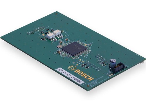
EB04 Expansion Board Digital Multichannel Potentiometer (F02U.005.592-01) for µLC Test System
- For the emulation of sensor data.
- Designed to work with sensor interfaces such as L9966 (FlexI).
- 4 independent, galvanically isolated, AC-capable channels.
- Max. voltage on any input referred to µLC-GND -24...+24 V.
- Wide range of resistances from 50 Ω to 500 kΩ (in steps of 1 Ω).
- High accuracy ±0.5 Ω ±1% and 19 bit resolution.
- Overcurrent protection.
- Non-mechanical solid-state switches.
Model Overview
| Model expansion board... | CAN-FD (EB07) | Digit Outputs (EB01) | Current Loop Interface (EB12) | Digital Multichannel Potentiometer (EB04) |
| Ordering code | F02U.005.545-01 | F02U.004.880-01 | F02U.004.844-01 | F02U.005.592-01 |
| Bundled with µLC Test System | F02U.V03.095-01 | F02U.V02.904-01 | F02U.V02.889-01 | F02U.V03.129-01 |
| Specifications | UBus, prot: ±56 V UCM: ±30 V RTerm: 120 Ω Max. data rate 1 Mbit/s (CAN), 5 Mbit/s (CAN-FD) Filter: Range filter for 11-bit and 29-bit IDs Resolution timestamp: 1 ms Adjustable cycle times 1 ms...65 s |
Application: Output voltage µLC 3.1 min. -1 V/max. 24 V |
TS: Engine speed -3,000...12,000 U/min Local pattern/teeth 48...60 Signal duration forward 35...55 µs/backward 80...100 µs Gaps 0...10 Prefixed bit 35...45 (de)activatable Signal period 737,000 µs Signal duration (stand still) 1,340...1,540 µs Signal period (stand still) 150,000 µs (de)activatable |
Application: Emulation of sensor data |
| Max. data rate 1 Mbit/s (CAN), 5 Mbit/s (CAN-FD) Filter: Range filter for 11-bit and 29-bit IDs Resolution timestamp: 1 ms Adjustable cycle times 1 ms...65 s |
DC characteristics: Uout output = low: <1.1 V Uin-Uout output = high <1.8 V Rout output = high-Z >10 MΩ Iout, prot channel shutdown threshold ±1 A SIout, prot shutdown threshold total current all outputs ±3.33 A |
AK: Engine speed -3,125...3,125 U/min Local pattern/teeth 48...60 Parity even/odd LR-Bit, LM0-Bit, LM1-Bit,LM2-Bit (de)activatable Signal period (stand still) 150,000 µs |
4 independent, galvanically isolated, AC-capable channels; max. voltage at any input referred to µLC-GND -24...+24 V Resistance from 50 Ω to 500 kΩ in steps of 1 Ω Accuracy ±0,5 Ω ±1% 19 bit resolution Overcurrent protection Non-mechanical solid-state switches | |
| Time measured at Uin = 24 V: trise load of 500 Ω to GND: 58 µs; load of 500 Ω to 24 V: 0.3 µs/without load: 62 µs; tfall load of 500 Ω to GND: 0.8 µs/load of 500 Ω to 24 V: 5.5 µs/without load: 12 µs; trestart 33.6 ms (restart time after over current) |
PWM-i: Engine speed -2,500...2,500 U/min Local pattern/teeth 48...60 Signal duration LR 35...55 µs (de)activatable/DR_L 80...100 µs/DR_R 170...190 µs/DR_L_EL 350...370 µs (de)activatable/DR_R_EL 710...730 µs (de)activatable Signal duration (stand still) 1,430...1,450 µs Signal period (stand still) 737,000 µs | |||
| PWM-s: Engine speed -5,000...5,000 U/min Local pattern/teeth 48...60 | ||||
| For use with | µLC Test System | µLC Test System | µLC Test System | µLC Test System |

Information on product safety:
Manufacturer:
Bosch Engineering GmbH, Robert-Bosch-Allee 1, 74232 Abstatt/DEU
www.bosch-engineering.com