Bosch µLC Test System Hardware-in-the-Loop Test System
Benefits of the Expandable Bosch µLC Test System HiL (MicroLC F02U.V02.303-02)
- Compact, space-saving, easy PC connectivity via USB.
- Simulation of typical automotive interfaces, sensors and protocols, including SENT, CAN, LIN.
- Use also for the development of controls in many other areas.
Bosch µLC Test System Hardware-in-the-Loop
The compact HiL system Bosch µLC Test System is an open-loop test system for quality assurance of control unit development, especially for mobile automotive applications, but also for other areas of control technology such as embedded, power electronics, consumer electronics, machine and plant engineering. It combines the simulation of all typical automotive sensors and communication protocols in one unit, such as analogue/digital inputs and outputs, PWM signals, SENT, CAN, LIN, and speed sensors. An initial test setup typically takes under ten minutes. Due to an intuitive user interface the operation of the device and data evaluation is easy.
- 8 analog outputs 10 bit and 4 analog outputs 12 bit (0 to 5 V, max. 5 mA).
- 6 analog inputs 12 bit, 0 to 40 V.
- 6 digital outputs.
- 2 relays, max. 10 A.
- 2 PWM inputs (1 Hz to 20 kHz), 4 PWM outputs (0.1 Hz to 20 kHz).
- Vehicle busses: 2x CAN, LIN, SENT.
- Engine speed simulation up to 20,000 rpm.
Various sensors, up to 2 crankshafts, up to 4 camshafts, auxiliary shaft.
Oscilloscope trigger signal for easier monitoring.
Error simulation for engine position management EPM. - Throttle body simulation.
- Cylinder pressure simulation: Up to 8 cylinders with one device, expandable with multiple devices.
- USB connection completely galvanic decoupled.
- All in- and outputs short-circuit protected and ESD protected.
- EMC tested.
- Different versions with expansion boards for additional HW features.
- Multi device support with sync option for engine speed signals.
Model Overview
| Model | Bosch µLC Test System |
| Analogue outputs | 8x 10 bit DAC 0...5 V, max. 5 mA internal or external supply 4x 12 bit DAC 0...5 V, max. 5 mA |
| Analog inputs | 6x 12 bit ADC 0...40 V, GND reference |
| Digital-I/O | 6x digital uut, max. 200 mA in total; output modes: Ground, 12 V, High impedance 2x relays, max. 10 A, separate ECU power supply possible and incl. main relay sensing 2x PWM input, 1 Hz...20 kHz 4x PWM output, max. 90 mA in total, 0.1 Hz...20 kHz, output voltages: 12 V, 5 V, GND Complex PWM with sub signals, each separately adjustable in frequency, duty cycle and pulse count |
| I/O connectors | 2 mm lab plugs |
| Vehicle busses | 2x CAN, up to 1 Mbit/s, switchable 120 Ω CAN bus terminator); LIN (Master/Slave); SENT (full J2716 Jan. 2012 standard, 4 outputs, alternative to PWM output) |
| Engine speed simulation | Up to 20,000 rpm; supported sensors: Hall, inductive, DG23i, TL4953; up to 2 crankshafts, up to 4 camshafts (each is independently configurable); auxiliary shaft; -180...180° camshaft adjustment |
| Interface | USB 2.0 FullSpeed, completely galvanic decoupled |
| Power supply | 12 VDC; typ. <1 A; ECU voltage 12 V/24 VDC, ECU current 10 A |
| Dimensions (mm) | 175 x 107 x 61; 690 g; Aluminum housing |
| Software | MicroLC Software for Windows 10 incl. Software updates and support are included in the first year after purchase, after that they can be added once a year if required via the µLC Test System Update and Support Subscription (article F02U.V02.838.01n) |
Versions
| Ordering code | Description |
| F02U.V02.303-02 | µLC Test System |
| F02U.V02.904-01 | µLC Test System + Expansionboard EB01 Digital Outputs |
| F02U.V03.129-01 | µLC Test System + Expansionboard EB04 Digital Multichannel Potentiometer |
| F02U.V03.095-01 | µLC Test System + Expansionboard EB07 CAN-FD |
| F02U.V02.889-01 | µLC Test System + Expansionboard EB12 Current Loop Interface |
Frequently Asked Questions:
Question: What is Hardware-in-the-Loop?
Answer: Hardware-in-the-loop (HiL) is a process in which a real environment is simulated for testing of a component (e.g. a control system). For example, to test a car engine control system, the car is simulated using a model. For this purpose, the HiL simulator must provide the appropriate inputs and outputs with which it can be connected to the control system in order to simulate the behavior of the vehicle in reality and in real time. Frequently recurring processes can be simulated particularly well in this way. The HiL simulator is thus a computer system that simulates the behavior of an environment by receiving and delivering data via interfaces and analog and digital input/output channels, just as sensors/actuators would do in the real environment. This creates the control "loop". The principle can already be used during development. In the optimal case, it shortens the development time and saves costs. The consistent, unchanging test environment of a HiL system can reliably demonstrate the elimination of a fault. However, a simulation usually cannot reproduce reality down to the last detail, so tests on the real system are of course still necessary.
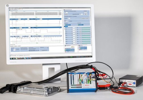
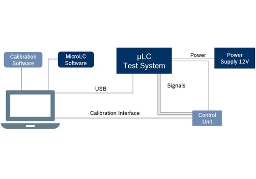
Question: What does a typical HiL test setup with the Bosch µLC Test System look like?
Answer: The Bosch µLC Test System is connected to a PC/laptop via USB. The laptop has two tasks: It calibrates the system under test (control unit) via appropriate software and it uses the Bosch MircoLC software to operate the µLC Test System. For the actual "loop", the µLC Test System is connected to the control unit under test via its interfaces and I/O channels. In addition, the µLC Test System is connected to a supply power. In the data sheet and the pictures above you will find an illustration of the test setup.
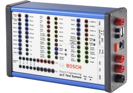
Question: Which I/O channels does the Bosch µLC Test System offer?
Answer: The Bosch µLC Test System supports the CAN/CAN-FD, LIN, and SENT interfaces commonly used in the automotive sector. In addition, there are 12 analog outputs (8x 10 bit/4x 12 bit, range 0 to 5 V/5 mA) and 6 analog inputs (12 bit, 0 to 40 V). For controlling switching operations, 6 digital outputs and 2 relay channels are available. These channels are supplemented by 2 PWM inputs and 4 PWM outputs (pulse width modulation), as used, for example, for controlling motors. Especially for automotive use, speed, throttle and cylinder pressure simulations are possible. In addition, the system can be expanded with the available expansion boards.
Information on product safety:
Manufacturer:
Bosch Engineering GmbH, Robert-Bosch-Allee 1, 74232 Abstatt/DEU
www.bosch-engineering.com


Related Products