| Model | Type | Channels | Technical specifications |
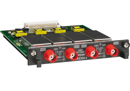
| MR8901 | Analog unit | 4 |
- Voltage measurement, DC...100 kHz bandwidth.
- Isolated BNC connector (input resistance 1 MΩ, input capacitance 10 pF).
- Max. rated voltage to earth: 100 VAC, DC (with input isolated from the main unit, the max. voltage that can be applied between input channel and chassis and between input channels without damage).
- Measurement range 5 mV...10 V/div, 11 ranges, full scale: 20 div.
AC voltage can be measured/displayed up to 140 VRMS at x1/2 amplitude compression, but limited to 100 VRMS according as max. rated voltage to earth.
- Low-pass filter 5/50/500 Hz, 5 kHz, OFF.
- Resolution 1/1250 of measurement range (using 16-bit A/D converter).
- Highest sampling rate 500 kS/s (simultaneous sampling across 4 channels).
- Accuracy ±0.5% of full scale (with filter 5 Hz, zero position accuracy included).
- Frequency characteristics DC...100 kHz -3 dB.
- Input coupling DC/GND.
- Max. allowable input 150 VDC (the max. voltage that can be applied across input pins without damage.
- Dimensions (mm) 120 x 19 x 152; 180 g.
|
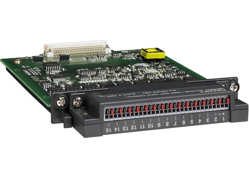
| MR8902 | Voltage/temperature unit | 15 |
- Voltage measurement, thermocouple measurement.
- Input connectors voltage/thermocouple input: push button terminal; recommended wire diameter: single-wire φ 0.32...0.65 mm, stranded wire 0.08...0.32 mm2 (conductor wire diameter min. φ 0.12 mm), AWG 28 to 22; input resistance 1 MΩ; max. rated voltage to earth: 100 VAC, DC (with input isolated from the main unit, the max. voltage that can be applied between input channel and chassis and between input channels without damage).
- Voltage measurement ranges 500 µV...5 V/div, 9 ranges, full scale: 20 division.
The AC instantaneous voltage waveform cannot be measured due to the slow sampling speed.
Resolution: 1/1000 of measurement range (using 16-bit A/D converter).
Accuracy: ±0.1% f.s. (with digital filter ON, zero position accuracy included).
- Temperature measurement reference junction compensation: Internal/ External (selectable); thermocouple broken-wire detection: ON/OFF (selection applies to entire unit).
Thermocouple type: J, K, T, E, R, S, B, N, WRe5-26.
For thermocouple measurement ranges, resolution, and accuracy, refer detailed datasheet.
- Digital filter 50 Hz, 60 Hz, or OFF.
- Data refresh rate 10 ms (with filter OFF, burn-out detection OFF); 20 ms (with filter OFF, burn-out detection ON); 500 ms (with filter ON, data refresh rate: Fast); 2 s (with filter ON, data refresh rate: Normal).
- Max. allowable input 100 VDC (the max. voltage that can be applied across input pins without damage).
- Dimensions (mm) 120 x 19 x 185; 190 g.
- Included accessories: 2x ferrite clamps.
|
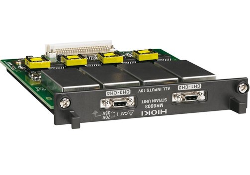
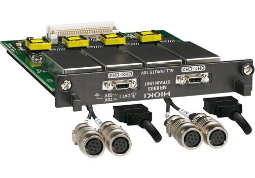
| MR8903 | Strain unit | 4 |
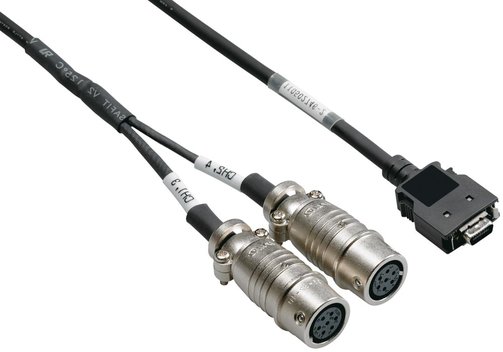
- Voltage/strain gauge converter input (conversion cable included); selectable for each channel, electronic auto-balancing, balance adjustment range within ±10000 µV, ±10000 µε.
- Input connectors "HDR-EC14LFDTG2-SLE+" (Honda Tsushin Kogyo Co.), via conversion cable, "PRC03-12A10-7M10.5" (Tajimi Electronics Co.); max. rated voltage to earth: 30 VACRMS or 60 VDC (with input isolated from the main unit, the max. voltage that can be applied between input channel and chassis and between input channels without damage).
- Suitable transducer: Strain gauge converter, bridge resistance 120 Ω...1 kΩ, bridge voltage: 2 V ±0.05 V, gauge rate: 2.0.
- Input resistance more than 1 MΩ.
- Voltage measurement ranges 50...1000 µV/div, 5 ranges, full scale: 20 division; accuracy: ±0.5% f.s. + 4 µV (at 50 µV/div only), other ranges ±0.5% f.s. (after auto-balance, with filter 5 Hz, zero position accuracy included).
- Strain measurement ranges 20...1000 µε/div, 6 ranges, full scale: 20 division: accuracy: ±0.5% f.s. + 4 µε (at 20, 50 µε/div), other ranges ±0.5% f.s. (after auto-balance, with filter 5 Hz, zero position accuracy included).
- Low-pass filter 5/10/100 Hz, 1 kHz, OFF
- Resolution 1/1250 of measurement range (using 16-bit A/D converter).
- Highest sampling rate 200 kS/s (simultaneous sampling across 4 channels).
- Frequency characteristics DC...20 kHz +1/-3 dB.
- Max. allowable input 10 VDC (the max. voltage that can be applied across input pins without damage).
- Dimensions (mm) 120 x 19 x 152; 173 g./li>
- Included accessories: 2x conversion cable (connector: TAJIMI PRC03-12A10-7M10.5).
|
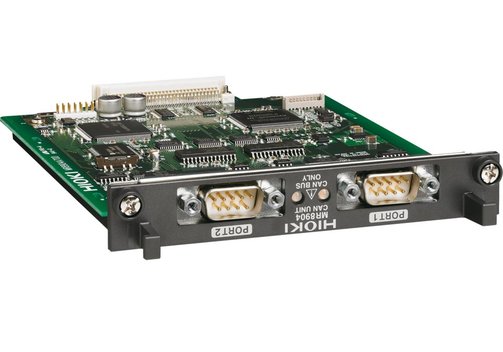
| MR8904 | CAN unit | Up to 15 |
- Connectors: 2x 9-pin D-sub male.
- ISO 11898 CAN 2.0b, ISO 11898-1, ISO 11898-2, ISO 11898-3, SAE J2411.
- Interface selectable: High-speed CAN, low-speed CAN, or single-wire CAN by port (with built-in corresponding transceiver).
- Transmit ACK ON/OFF for transmitting a ACK for receiving CAN signal with the MR8904.
- Terminator ON/OFF via commands, 120 Ω ±10 Ω built-in resistance.
- Baud rate 50 kbps...1 Mbps at "high-speed", 10...125 kbps at "low-speed", 10...83.3 kbps at "single-wire".
- Analyzed signal output channel: Up to 15 analog channels each equivalent to a 16-bit analog signal; up to 16 logic channels each equivalent to a 1-bit logic signal.
- Signal form, 1-bit signal: 1 channel of logic, or 1 channel of analog; 1-bit to 16-bits signal: 1 channel of analog, 17-bits to 32-bits signal: 2 channels of analog.
Cannot handle signals over 32-bits.
- ID trigger output "H" level pulse to designated logic channel when receiving set ID signal.
Output pulse width: 50 µs below 5 ms/div time axis, 1 sampling time at more than 10 ms/div time axis.
- Response time within 200 µs after completely receiving CAN message.
- Transmit CAN message: Can transmit the setting CAN message to the CAN bus by a port.
- Dimensions (mm) 120 x 19 x 152; 185 g.
|
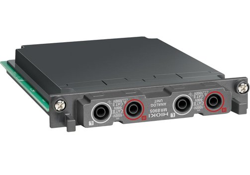
| MR8905 | Analog unit | 2 |
- Channels switchable between high voltage DC instantaneous value and AC RMS value; DC...100 kHz bandwidth.
- Input Banana connector (input impedance 4 MΩ, input capacitance less than 1 pF).
- Max. rated voltage to earth: CAT II 1000 VAC and DC, CAT III 600 VAC and DC
- Measurement range 500 mV...50 V/div, 7 ranges, full scale: 20 div.
The maximum displayable AC voltage is 700 VRMS when using 1/2 compression of the vertical axis.
- Low-pass filter 5/50/500/5 kHz, OFF.
- Resolution 1/1250 of measurement range (using 16-bit A/D converter).
- Highest sampling rate 500 kS/s (simultaneous sampling across 2 channels).
- Accuracy ±0.5% f.s. (with 5 Hz filter ON).
- RMS measurement accuracy: ±1.5% f.s. (30 Hz up to but not including 1 kHz, sine wave input) or ±3% f.s. (1 kHz up to 10 kHz, sine wave input); response time: 300 ms (filter off, rising from 0...90% f.s.) or 600 ms (filter off, falling from 100...10% f.s.); crest factor 2.
- Frequency characteristics DC...100 kHz -3 dB.
- Input coupling DC/AC-RMS/GND.
- Max. allowable input 1000 VDC, 700 VAC (the max. voltage that can be applied across input pins without damage).
- Dimensions (mm) 120 x 19 x 152; 185 g.
|