Keysight 849x/8490x Series RF and Microwave Attenuators
Keysight Coaxial Fixed and Step Attenuators
The Keysight 849x/8490x Series coaxial fixed and step attenuators can be used in a wide variety of signal conditioning and level control applications. Attenuators are generally used to reduce signal levels, improve matching impedances of sources and loads, and measure the gain or loss of two-port devices.
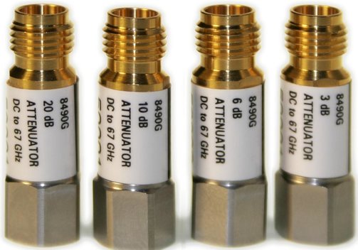
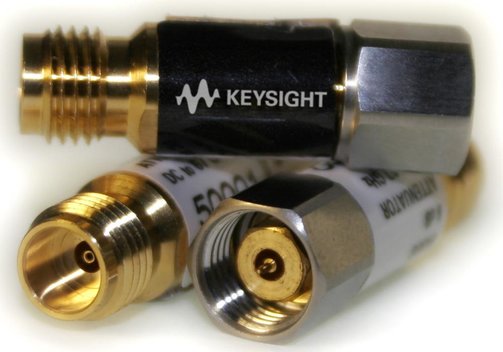
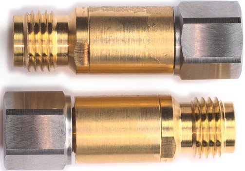
Keysight Coaxial Fixed Attenuators
Keysight Models 8490 D/G, 8491 A/B, 8493 A/B/C, 8498A
| Model | 8491A | 8493A | 8491B | 8493B | 8498A | 8493C | 8490D | 8490G | |
| Frequency | DC...12.4 GHz | DC...12.4 GHz | DC...18 GHz | DC...18 GHz | DC...18 GHz | DC...26.5 GHz | DC...50 GHz | DC...67 GHz | |
| Attenuation accuracy | |||||||||
| 3 dB | 0.3 | 0.3 | 0.3 | 0.3 | - | 1.0 | 4.8 | 4.8 | |
| 6 dB | 0.3 | 0.3 | 0.4 | 0.4 | - | 0.6 | 7.8 | 7.8 | |
| 10 dB | 0.5 | 0.5 | 0.6 | 0.6 | - | 0.5 | 11.3 | 11.3 | |
| 20 dB | 0.5 | 0.5 | 1.0 | 1.0 | - | 0.6 | 21.7 | 21.5 | |
| 30 dB | 1.0 | 1.0 | 1.0 | 1.0 | 1.0 | 1.0 | 31.7 | 31.7 | |
| 40 dB | 1.5 | - | 1.5 | - | - | 1.3 | 42.5 | 42.5 | |
| 50 dB | 1.5 | - | 1.5 | - | - | - | - | - | |
| 60 dB | 2.0 | - | 2.0 | - | - | - | - | - | |
| Max. SWR | 1.30 | 1.30 | 1.50 | 1.50 | 1.30 | 1.25 | 1.45 | 1.45 | |
| Max. input average power | 2 W | 2 W | 2 W | 2 W | 25 W | 2 W | 1 W | 1 W | |
| Max. input peak power | 100 W | 100 W | 100 W | 100 W | 125 W | 100 W | 100 W | 100 W | |
| RF connectors | N (m, f) | SMA (m, f) | N (m, f) | SMA (m, f) | N (m, f) | 3.5 mm (m, f) | 2.4 mm (m, f) | 1.85 mm (m, f) | |
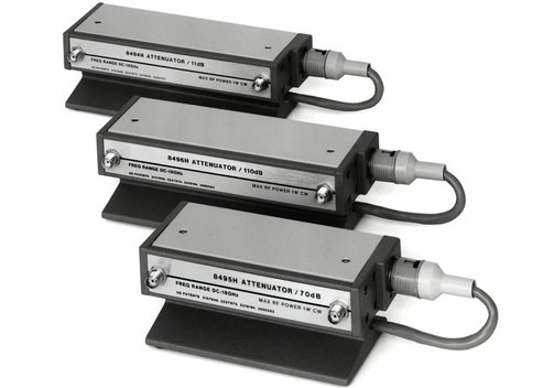
Keysight Manual Step Attenuators
Keysight Models 8494 A/B, 8495 A/B/D, 8496 A/B
| Model | 8494A | 8495A | 8496A | 8494B | 8495B | 8496B | 8495D |
| Frequency | DC...4 GHz | DC...4 GHz | DC...4 GHz | DC...18 GHz | DC...18 GHz | DC...18 GHz | DC...26.5 GHz |
| Attenuation range | 0...11 dB | 0...70 dB | 0...110 dB | 0...11 dB | 0...70 dB | 0...110 dB | 0...70 dB |
| Attenuation step | 1 dB | 10 dB | 10 dB | 1 dB | 10 dB | 10 dB | 10 dB |
| Insertion loss at 0 dB | 0.96 dB | 0.68 dB | 0.96 dB | 2.22 dB | 1.66 dB | 2.22 dB | 3.95 dB |
| Max. SWR | 1.50 | 1.35 | 1.50 | 1.90 | 1.70 | 1.90 | 2.20 |
| Max. input average power | 1 W | 1 W | 1 W | 1 W | 1 W | 1 W | 1 W |
| Max. input peak power | 100 W | 100 W | 100 W | 100 W | 100 W | 100 W | 100 W |
| Operating life (n million cycles/section) | 5 | 5 | 5 | 5 | 5 | 5 | 5 |
| Repeatability (5 million cycles per section) | 0.03 dB | 0.03 dB | 0.03 dB | 0.03 dB | 0.03 dB | 0.03 dB | 0.03 dB to 18 GHz, 0.05 dB to 26.5 GHz |
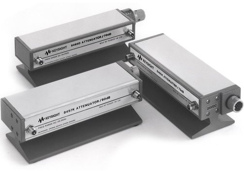
Keysight Programmable Step Attenuators
Keysight Models 8494 G/H, 8495 G/H/K, 8496 G/H
| Model | 8494G | 8495G | 8496G | 8494H | 8495H | 8496H | 8495K | 8497K |
| Frequency | DC...4 GHz | DC...4 GHz | DC...4 GHz | DC...18 GHz | DC...18 GHz | DC...18 GHz | DC...26.5 GHz | DC...26.5 GHz |
| Attenuation range | 0...11 dB | 0...70 dB | 0...110 dB | 0...11 dB | 0...70 dB | 0...110 dB | 0...70 dB | 0...90 dB |
| Attenuation step | 1 dB | 10 dB | 10 dB | 1 dB | 10 dB | 10 dB | 10 dB | 10 dB |
| Insertion loss at 0 dB | 0.96 dB | 0.68 dB | 0.96 dB | 2.22 dB | 1.66 dB | 2.22 dB | 3.95 dB | 2.79 dB |
| Max. SWR | 1.50 | 1.35 | 1.50 | 1.90 | 1.70 | 1.90 | 2.20 | 1.80 |
| Max. input average power | 1 W | 1 W | 1 W | 1 W | 1 W | 1 W | 1 W | 1 W |
| Max. input peak power | 100 W | 100 W | 100 W | 100 W | 100 W | 100 W | 100 W | 100 W |
| Operation life (n million cycles/section) | 5 | 5 | 5 | 5 | 5 | 5 | 5 | 5 |
| Repeatability | 0.03 | 0.03 | 0.03 | 0.03 | 0.03 | 0.03 | 0.03 to 18 GHz, 0.05 to 26.5 GHz | 0.03 to 18 GHz, 0.05 to 26.5 GHz |
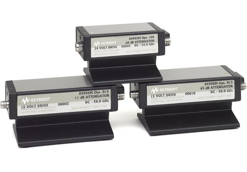
Keysight Models 84904 K/L/M, 84905M, 84906 K/L, 84907 K/L, 84908M
| Model | 84906K | 84907K | 84904L | 84906L | 84907L | 84904M | 84905M | 84908M |
| Frequency | DC...26.5 GHz | DC...26.5 GHz | DC...40 GHz | DC...40 GHz | DC...40 GHz | DC...50 GHz | DC...50 GHz | DC...50 GHz |
| Attenuation range | 0...90 dB | 0...70 dB | 0...11 dB | 0...90 dB | 0...70 dB | 0...11 dB | 0...60 dB | 0...65 dB |
| Attenuation step | 10 dB | 10 dB | 1 dB | 10 dB | 10 dB | 1 dB | 10 dB | 5 dB |
| Insertion loss at 0 dB | 1.86 dB | 1.40 dB | 2.40 dB | 2.40 dB | 1.80 dB | 3.00 dB | 2.60 dB | 3.00 dB |
| Max. SWR | 2.00 | 1.90 | 2.00 | 2.00 | 1.90 | 3.00 | 2.60 | 3.00 |
| Max. input average power | 1 W | 1 W | 1 W | 1 W | 1 W | 1 W | 1 W | 1 W |
| Max. input peak power | 50 W | 50 W | 50 W | 50 W | 50 W | 50 W | 50 W | 50 W |
| Operation life (n million cycles/section) | 5 | 5 | 5 | 5 | 5 | 5 | 5 | 5 |
| Repeatability | 0.03 | 0.03 | 0.03 | 0.03 | 0.03 | 0.03 | 0.03 | 0.03 |
Options on request, please call.
Frequently Asked Questions:
Question: What is an attenuator?
Answer: An attenuator is connected into a signal path and reduces the signal level or amplitude. The attenuation is constant over a wide frequency range (in contrast to frequency-dependent circuits such as filters). Attenuation is expressed in dB (decibels), a logarithmic auxiliary unit of measure for the ratio of two similar quantities. In the simplest case, an attenuator is a voltage divider. For higher frequency applications, impedance matching must also be considered: In the RF range, input and output impedance must be equal to the wave impedance of the lines.
Question: What is a step attenuator?
Answer: Fixed attenuators have a fixed attenuation. In contrast, step attenuators are switchable combinations of attenuators that can be used to set a desired attenuation. Depending on the design, the setting can be made manually or can be programmed via an interface.

Information on product safety:
Manufacturer:
Keysight, 1400 Fountaingrove Parkway, Santa Rosa, CA/USA
www.keysight.com
(Keysight Technologies Deutschland GmbH)