


Rigol SPQ Array Measurement and Control Solution


Benefits of the SPQ Modular Microwave Digital Measurement and Control System
- Flexible configurations for microwave control and measurement systems with 100 to 1000 channels.
- 14 bit and max. sample rate 10 GS/s (transmit channels)/5 GS/s (receive channels).
- Multi-device synchronization with low phase drift.
Rigol SPQ Array Measurement and Control Solution
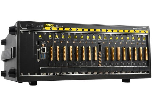
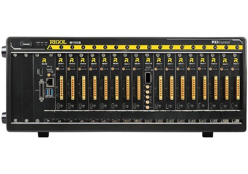
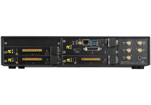
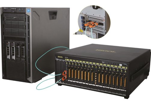
The Rigol SPQ modular array measurement and control solution is designed for complex physical experiments. The system has a modular architecture that is divided into the platform, service module and synchronous triggering module. Users can flexibly configure the required service modules based on experimental requirements to construct various types of complex experimental systems. This modular architecture also facilitates system upgrades and expansion as needed. The system supports rapid deployment of microwave control and measurement systems with 100 to 1000 channels.
- Digital measurement and control with flexible configuration thanks to modular design.
- High sample rate: Generate RF control signals within the second Nyquist zone, with a maximum sample rate of 10 GS/s for transmit channels and 5 GS/s for receive channels.
- High integration density: A single 4U 19" device integrates 128 measurement and control channels, and a single cabinet can deploy thousands of measurement and control channels.
- Multi-device synchronization for thousands of measurement and control channels of dozens of devices that can work simultaneously, with phase drift less than ±5 ps.
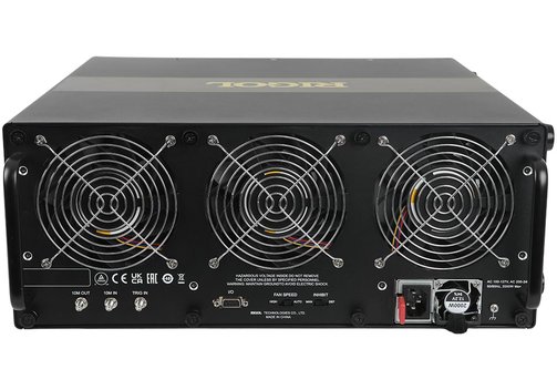
- Low noise fan.
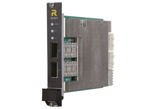
- Convergence computing: PXIe-to-PCIe bridge enables the server to control measurement and control device service boards via PCIe, and supports remote fiber optic connections. The collected data can be transferred to servers via low-latency and high-bandwidth DMA.
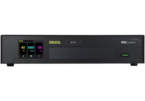
Model Overview - Control Platform
| Model | M1103B PQ-C16 | M1210 PQ-C02 |
| Description | Measurement and control platform | Small-scale measurement and control platform |
| Number of supported service modules | 16 | 2 |
| Dimensions (mm) | 19"/4U; 444 x 178 x 481; approx. 20 kg (related to the number of modules) | 340 x 68 x 230; approx. 5 kg |
| Power supply | Input voltage AC 100...240 V, static 75 W, max. power consumption 1300 W at 220 V power supply | Input voltage DC 19.5 V, with adaptor (100...240 V); max. power consumption 180 W |
| Fan noise | Less than 60 dB | - |
| System integration density | 128 channels/4U | Applicable to 8-bit small-scale measurement and control application or demonstration prototypes |
| Delay | Intra-module feedback delay <280 ns (PQ-MC module channel based); intra-chassis feedback delay <500 ns; inter-chassis feedback selay <650 ns | Intra-module feedback delay <280 ns (PQ-MC module channel based) |
Model Overview - Controller and Clock Synchronization
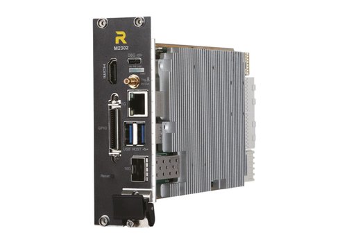
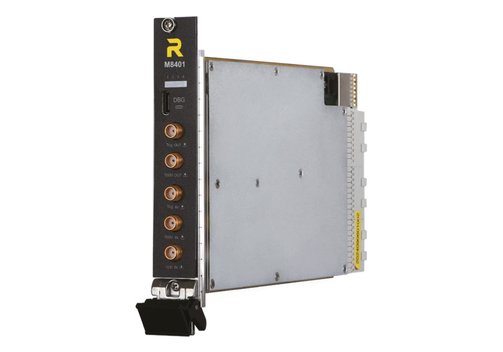
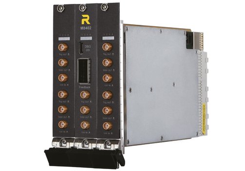
| Model | M2302 PQ-M02 | M2601 PQ-R01 | M8401B PQ-S10 | M8402B PQ-S10 |
| Description | Controller | Remote controller | Clock synchronization module | Clock synchronization module, for parallel synchronization among multi-chassis modules |
| Basic specifications | Processor core parameters AMD V2000 or equivalent CPU, with 10 GbE, memory: 32 GB, 4800 MHz; storage capacity built-in 512 GB SSD, expansion supported; interface USB 3.0, Gigabit Ethernet RJ45, HDMI or DP port; operating system CentOS 8 | Connector parameters QSFP X2, fiber interface, supports PCIe Gen3 X8 protocol conversion; max. fiber length >50 m; module characteristics: PXIe-to-PCIe bridge, direct control of measurement devices by HPC server; Convergence Computing supported, CPU to QPU communication latency <25 µs, >6.6 GB/s | 16 backplane clock distributions; clock mode: Internal phase-locked crystal oscillator/external front panel clock input; internal clock: Internal phase-locked crystal oscillator, 100 MHz; internal clock stability ≤10 ppb; 16 backplane trigger distributions; trigger step 80 ns/800 ns; number of triggers 1 to ∞; 16-link feedback connections to modules in the chassis backplane | 16 backplane clock distributions); clock mode: Internal phase-locked crystal oscillator/external front panel clock input; internal clock: Internal phase-locked crystal oscillator, 100 MHz; internal clock stability ≤+0.3 ppm; 16 backplane trigger distributions; trigger step 80 ns/800 ns; number of triggers 1 to ∞; 16-link feedback connections to modules in the chassis backplane; front panel supports inter-chassis feedback interconnections with QSFP/QSFP-DD/MPO |
Model Overview - Modules
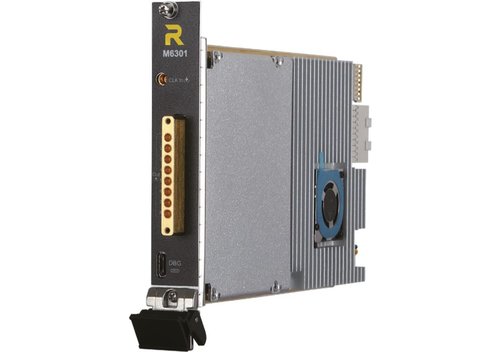
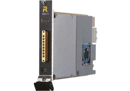
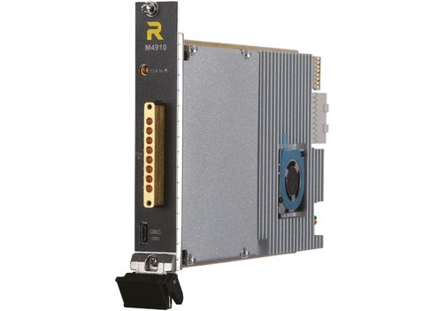
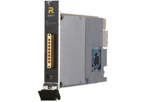
| Model | M6301 PQ-XY | M6311 PQ-ZC | M4910 PQ-RD | M4911 PQ-MC |
| Description | Microwave controller module | Bias control module | Microwave readout module; supports reading of 4 independent links per module | Microwave measurement and control module; a single module can control and read multiple bits on one link |
| Channel number | 8, AC-coupled | 8, DC-coupled | 4 microwave excitation channels (AC-coupled) | 1 microwave excitation channel (AC-coupled); 6 microwave control channels (AC-coupled) |
| Output frequency range | 0.1...9.8 GHz | DC...1.8 GHz | 0.1...9.8 GHz | 0.1...9.8 GHz |
| DAC resolution | 14 bit | - | 14 bit | 14 bit |
| DAC sample rate | 4/6/8/10 GS/s | 2/4/6 GS/s | 4/6/8/10 GS/s | 4/6/8/10 GS/s |
| SFDR | -50 dBc at 4.3 GHz | -70 dBc at 500 MHz | -50 dBc at 4.3 GHz | -50 dBc at 4.3 GHz |
| Memory depth | Waveform AWG mode 600 kpts/channel; instruction set mode 100 kpts/channel | Waveform AWG mode 300 kpts/channel; instruction set mode 100 kpts/channel | Waveform combination mode 48 kpts/channel; AWG mode 600 kpts/channel; instruction set mode 100 kpts/channel | Waveform combination mode 48 kpts/channek; AWG mode 600 kpts/channel; instruction set mode 100 kpts/channel |
| Channel number | - | - | 4 microwave acquisition channels (AC-coupled) | 1 microwave acquisition channel (AC-coupled) |
| Input frequency range | - | - | 0.1...9.8 GHz | 0.1...9.8 GHz |
| ADC resolution | - | - | 14 bit | 14 bit |
| ADC sample rate | - | - | 3/4/5 GS/s | 3/4/5 GS/s |
| SFDR | - | - | 53 dBc at 4.3 GHz | 53 dBc at 4.3 GHz |
| Memory depth | - | - | Max. 8 kpts/channel | Max. 8 kpts/channel |
| Number of demodulation frequency points | - | - | Combination mode: 8 pts/channel; 16 pts/channel | Combination mode: 8 pts/channel; 16 pts/channel |
| Data upload type | - | - | Raw data/demodulated IQ data/decision result data | Raw data/demodulated IQ data/decision result data |

Information on product safety:
Manufacturer:
RIGOL Technologies CO., LTD., No.8 Ke Ling Road, Suzhou New District 21516/CHN
www.rigol.com
(EU branch Germany)