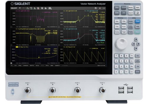
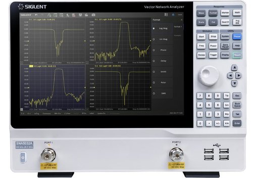
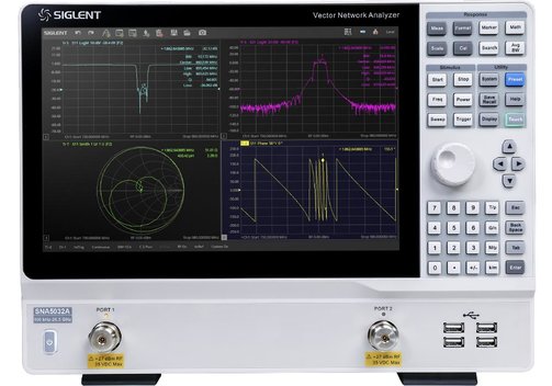
Siglent SNA5000A Vector Network Analyzer Series up to 26.5GHz

Benefits of the Siglent SNA5000A Series VNA with 2 or 4 Channels
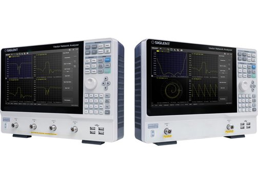
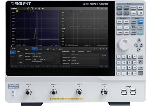
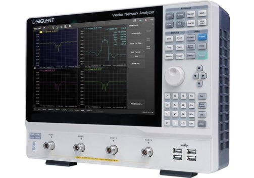
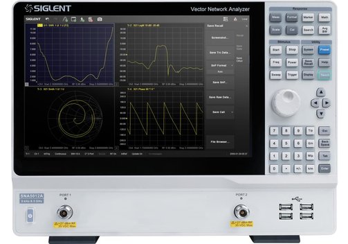
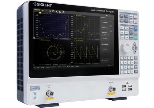
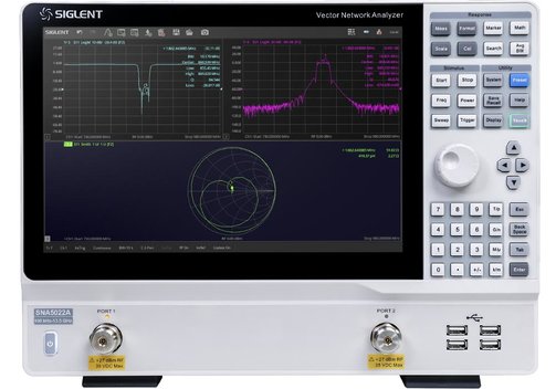
- 2- or 4-port VNAs up to 4.5 or 8.5 GHz, 2-port up to 13.5 or 26.5 GHz.
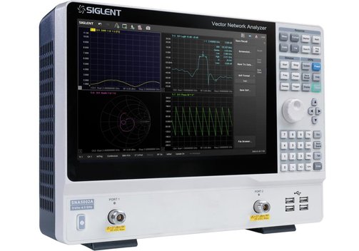
- Wide touch screen display with intuitive user interface.
- Variety of versatile measurement, calibration and display types.
Siglent SNA5000A Vector Network Analyzer Series up to 26.5 GHz
Models Siglent SNA5002A, SNA5012, SNA5004A, SNA5014A, SNA5022A, SNA5032A
With the SNA5000A series of VNA (vector network analyzers) Siglent enters a new level of high quality instrumentation. The devices are an accurate solution for many applications in advanced RF test and measurement such as embedded design, wireless design, RF device testing and power electronics. The devices have a frequency range of 9 kHz to 4.5 or 8.5 GHz, or 100 kHz to 13.5 or 26.5 GHz. They support 2- or 4-ports scattering-parameter, differential-parameter, and time-domain parameter measurements. The SNA5000A VNAs are powerful and precise instruments for determining the Q-factor, bandwidth and insertion loss of a filter. The devices also feature impedance conversion, movement of measurement plane, limit testing, ripple test, fixture simulation and adapter removal/insertion adjustments. The SNA5000 series VNAs have five sweep types: Linear frequency mode, log frequency mode, power sweep mode, CW time mode, and segment sweep mode. The instruments also support scattering-parameter correction of SOLT, SOLR, TRL, Response and Enhanced Response for optimal flexibility in manufacturing as well as R&D applications.
- Vector network analyzers (VNA) with 2 or 4 channels, support 2 or 4-ports scattering-parameter.
- Frequency range 9 kHz to 4.5 GHz or 8.5 GHz, or 100 kHz to 13.5 GHz or 26.5 GHz.
- Frequency resolution 1 Hz.
- Level resolution 0.05 dB.
- Range of IFBW 10 Hz to 3 MHz.
- Setting range of output level -55...+10 dBm.
- Dynamic range 125 dB.
- Various types of calibration: Response calibration, enhanced response calibration, full-one port calibration, full-two port calibration, full-three port calibration, full-four port calibration, TRL calibration.
- Various types of measurements (some of them optional): Scattering parameter measurement, differential parameter measurement, receiver measurement, time domain parameter analysis, limit test, ripple test, impedance conversion, fixture simulation , adaptor removal insertion , spectrum analysis, frequency offset, scalar mixer measurement.
- Bias-Tees supported.
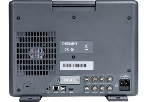
- Interfaces: Ethernet/LAN and USB Host & Device, optional USB-to-GPIB adaptor.
- Remote control: SCPI, LabVIEW, IVI based on USB-TMC, VXI-11, Socket, Telnet, WebServer.
- Wide 12.1"/30.7 cm touch screen and HDMI video output.
Model Overview
| Model | SNA5002A | SNA5012A | SNA5004A | SNA5014A | SNA5022A | SNA5032A |
| Frequency range | 9 kHz...4.5 GHz | 9 kHz...8.5 GHz | 9 kHz..4.5 GHz | 9 kHz...8.5 GHz | 100 kHz...13,5 GHz | 100 kHz...26,5 GHz |
| Ports | 2 | 2 | 4 | 4 | 2 | 2 |
| Frequency resolution | 1 Hz | |||||
| Level resolution | 0.05 dB | |||||
| Range of IFBW | 10 Hz...3 MHz | |||||
| Setting range of output level | -55...+10 dBm | |||||
| Dynamic range (IFBW 10 Hz, values: Specification and SPD) | 85 dB/102 dB (9...18 kHz); 90 dB/105 dB (18...30 kHz); 95 dB/107 dB (30...100 kHz); 105 dB/117 dB (100...300 kHz); 120 dB/130 dB (300...500 kHz); 125 dB/136 dB (500 kHz...1 MHz); 125 dB/140 dB (1 MHz...5 GHz); 123 dB/133 dB (5...6.8 GHz); 120 dB/130 dB (6.8...7.7 GHz); 119 dB/129 dB (7.7...8 GHz); 117 dB/127 dB (8...8.5 GHz) | 115 dB/125 dB (100 kHz...10 MHz); 125 dB/135 dB (10 MHz...3 GHz); 125 dB/135 dB (3...9 GHz); 118 dB/125 dB (9...13.5 GHz); 115 dB/125 dB (13.5...20 GHz); 105 dB/115 dB (20...26.5 GHz) | ||||
| Bias-tees | Standard | |||||
| Interface | LAN, USB Host & Device (USB 2.0); optional USB-to-GPIB | |||||
| Remote control | SCPI/LabVIEW/IVI based on USB-TMC/VXI-11/Socket/Telnet/WebServer | |||||
| Display | 12.1"/30.7 cm TFT LCD touch screen WXGA (1280x800); HDMI video output | |||||
| Types of calibration | Response calibration, enhanced response calibration, full-one port calibration, full-two port calibration, full-three port calibration, full-four port calibration, TRL calibration | |||||
| Types of measurement | Scattering-parameter measurement, differential-parameter measurement, receiver measurement, time-domain parameter analysis (option SNA5000-TDA), limit test, ripple test, impedance conversion, fixture simulation, adaptor removal/insertion, enhanced time-domain parameter analysis (option SNA5000-TDR), spectrum analysis (option SNA5000-SA), frequency offset, scalar mixer measurement (option SNA5000-SMM) | |||||
| Dimensions (mm) | 378 x 284 x 126; 2-port: 5.5 kg, 4-port and SNA5022A/SNA5032A: 7.4 kg | |||||
Included: SNA 5002A, 5004A, 5012A, 5014A, 5022A, 5032A, power cable, USB cable, quick start, calibration certificate, wireless mouse, protective cover.


Frequently Asked Questions:
Question: What does a VNA/vector network analyzer do?
Answer: Network analyzers are electronic measuring instruments for circuit development and test, especially in radio frequency (RF) technology. They are used to investigate the transmission characteristics of networks. Network does not mean a computer network, but a transmission element like amplifier, filter, cable etc. The scattering parameters (S-parameters) at the electrical ports are measured as a function of frequency. For example, a network analyzer determines the characteristic impedance and the attenuation of a transmission element as a function of frequency. A vector network analyzer (VNA), in contrast to an "ordinary" network analyzer, detects and observes the phase relationships of the signals under investigation.
Question: What are the S-parameters?
Answer: The S-parameters (abbreviation for scattering parameters) describe the behavior of linear components (cables, amplifiers, networks) in the small signal range. Two possible effects occur during signal transmission: Reflection and rejection/non-absorption of part of the incoming signal power. The reasons are junction/connection of lines with different characteristic impedances and mismatch. The effects only occur when a wave has formed on a line (hence the S-parameters are also referred to as wave magnitudes). In practice, the S-parameters are dimensionless complex numbers measured as a function of frequency. In RF technology, 2-ports (filters, amplifiers, etc.) are particularly common and important. In them, four S-parameters are of interest:
- S11 input reflection factor: Represents the match at the input of the device under test (DUT).
- S22 output reflection factor: Represents the match at the output of the DUT.
- S21 forward transmission factor: Represents the gain/attenuation of the DUT.
- S12 backward transmission factor: Represents the isolation of the input from the output of the DUT (i.e. what power appears at the input when a signal is applied to the output).
Question: What other parameters does a VNA measure besides the S paramters?
Answer: During signal transmission, two effects occur on the DUT: Reflection and transmission (or, conversely, rejection/non-absorption of part of the incoming signal power). The parameters analyzed by the VNA all depend on these two basic variables.
In the field of reflection, the parameters of interest are:.
- SWR (Standing Wave Ration in general) or specifically for electric charge VSWR (Voltage Standing Wave Ration) describes the correspondence of the impedance of a load connected to a line with the characteristic impedance of the line, or the ratio effective voltage of the forward/return wave; 1 for ideally no reflection, 8 for ideally full reflection.
- S-parameters S11 and S22 (see above).
- Reflection coefficient (amplitude ratio between "original" and reflected wave; 0 at ieal no reflection, 1 at ideal full reflecion).
- Impedance, admittance.
- Return loss (ratio of transmitted to reflected power; 8 dB at ideal no reflection, 0 dB at ideal full reflection).
In the field of transmission, the parameters are:
- Gain/loss.
- S-parameters S21, S12 (see above).
- Transmission coefficient (analogous to reflection coefficient).
- Insertion loss (attenuation of the signal through the DUT).
- Group delay (delay of the envelope of the signal (i.e. the various sinusoidal components of the signal) through a DUT).
Question: What is the difference between a spectrum analyzer and a VNA?
Answer: In simple terms, a VNA is usually used to examine the behavior of a DUT (component, assembly, circuit, device) in response to a known test signal: What does the DUT "do" with the known input test signal at its output (changes in amplitude, phase shifts, etc.)? To do this, a VNA requires one or more sources of the test signal as well as receivers. A spectrum analyzer, on the other hand, examines a (mostly "unknown") signal itself in the frequency domain (amplitude, sidebands, harmonics, etc.). The spectrum analyzer is therefore only a 1-channel receiver and does not contain a signal source.
Question: For which applications are the Siglent VNA SNA5002A, SNA5012A, SNA5004A, SNA5014A, SAN5022A, SNA5032A suitable??
Answer: The devices are suitable for measurement, characterization and test in the RF range up to 8.5 GHz, such as embedded design, wireless design, RF device testing and power electronics, with 2 or 4 ports depending on the model. The devices can measure parameters such as loss, transmission, phase, impedance, delay, time domain analysis etc.
Information on product safety:
Manufacturer:
SIGLENT Technologies CO., LTD., Blog No.4 & No.5, Antongda Industrial Zone, 3rd Liuxian Road, Bao’an District, Shenzhen, 518101/CHN
www.siglent.com
(EU branch Germany)


Customers also bought