CAMI/CableEye
New!

€
2.191,98

€
4.134,06

€
5.019,42

starting €
11.845,26


€
821,10
New!

€
976,99

€
1.207,85

€
4.134,06

starting €
706,86

€
441,49
CAMI/CableEye Test System for Cables and Wire Harnesses
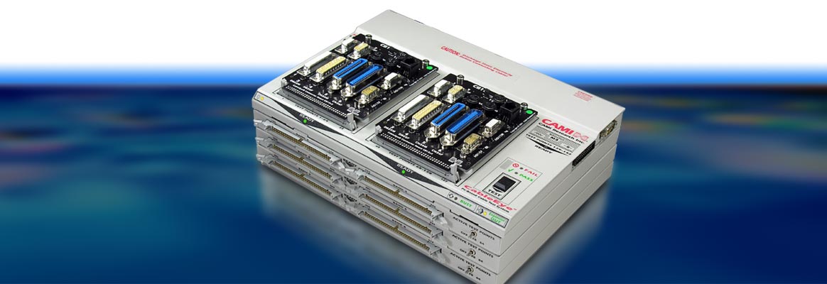
- CableEye accompanies you in all "life phases" of your cables. From the first design of new cables and prototypes to production, quality control/final test and daily use when reliable cables are required.
- CableEye is modular expandable and future-proof. From 128 up to 2560 test points. For testing of connection/continuity/line break, cable allocation/miswiring, resistance, insulation resistance, sporadically occurring errors and much more.
- CableEye provides the perfect test protocols for quality assurance and quality control.
Test and Measurement Matrix
| Model | ▸M2Z | ▸M3Z | ▸M4 | ▸HVX | ▸HVX-21 | |
| Continuity | Opens, shorts, miswires | ✓ | ✓ | ✓ | ✓ | ✓ |
| Intermittent faults | ✓ | ✓ | ✓ | ✓ | ✓ | |
| Complex networks, backplanes | ✗ | ✓ | ✓ | ✓ | ✓ | |
| Resistance | Connection, non-Connection quality | ✗ | ✓ | ✓ | ✓ | ✓ |
| Resistance (2-wire) | ✗ | ✓ | ✓ | ✓ | ✓ | |
| Continuous resistance scan | ✗ | ✓ | ✓ | ✓ | ✓ | |
| Fixture resistance nulling | ✗ | ✓ | ✓ | ✓ | ✓ | |
| Resistance (4-wire Kelvin) | ✗ | ✗ | ✓ | (✓) option | (✓) option | |
| High current resistance | ✗ | ✗ | ✓ | (✓) option | (✓) option | |
| Capacitance | Wire length, cable length | ✗ | ✗ | ✓ | (✓) option | (✓) option |
| Length to break | ✗ | ✗ | ✓ | (✓) option | (✓) option | |
| Twist pairing | ✗ | ✗ | ✓ | (✓) option | (✓) option | |
| Single channel safety test | Chassis, panels, transformers, etc. | ✗ | ✗ | ✗ | ✓ | ✓ |
| Insulation quality | Dielectric strength, withstand voltage | ✗ | ✗ | ✗ | ✓ | ✓ |
| Insulation resistance | ✗ | ✓ | ✓ | ✓ | ✓ | |
| Presence of contaminants | ✗ | ✗ | ✗ | ✓ | ✓ | |
| In-Line Components | Resistors | ✗ | ✓ | ✓ | ✓ | ✓ |
| Diodes - orientation | ✓ | ✓ | ✓ | ✓ | ✓ | |
| Diodes - forward voltage | ✗ | ✓ | ✓ | ✓ | ✓ | |
| LEDs - orientation | ✓ | ✓ | ✓ | ✓ | ✓ | |
| LEDs - color detection | ✗ | ✓ | ✓ | ✓ | ✓ | |
| Zener diodes - orientation | ✓ | ✓ | ✓ | ✓ | ✓ | |
| Zener diodes - forward voltage | ✗ | ✓ | ✓ | ✓ | ✓ | |
| Zener diodes - reverse breakdown voltage <10 V | ✗ | ✓ | ✓ | ✓ | ✓ | |
| Zener diodes - reverse breakdown voltage >10 V | ✗ | ✗ | ✗ | ✓ | ✓ | |
| Capacitors | ✗ | ✗ | ✓ | (✓) option | (✓) option | |
Model Overview and Features
| Model | Low voltage | Low voltage | Low voltage | High voltage | High voltage | Model |
| ▸MZ | ▸M3Z | ▸M4 | ▸HVX | ▸HVX-21 | ||
| ▸CAMI-814 | ▸CAMI-826 | ▸CAMI-824 | ▸CAMI-829 | ▸CAMI-829A | ||
| Control module test points | 128 | 128 + 24 accessory test points | 128 + 24 accessory test points | 128 + 24 accessory test points for LV tests, 128 for HV tests | 128 + 24 accessory test points for LV tests, 128 for HV tests | Control module test points |
| Max. test points | 128 | 2560 | 2560 | 1024 | 512 | Max. test points |
| Test time (128 test points) - continuity only | 0.20 s | 0.15 s | 0.15 s | From 0.20/0.15 s | From 0.20/0.15 s | Test time (128 test points) - continuity only |
| Test time (128 test points) - with resistance test | N/A | 0.40 s | 0.40 s | From 0.25/0.40 s | From 0.25/0.40 s | Test time (128 test points) - with resistance test |
| Resistance thresholds | 46 kΩ, fixed | 0.1 Ω...5 MΩ | 0.02 Ω...6 MΩ | 0.1/0.02 Ω...1 GΩ | 0.1/0.02 Ω...5 GΩ | Resistance thresholds |
| Resistance accuracy - 10Ω...100Ω | - | ±0.2Ω | ±0.15Ω | ±0.2Ω/±0.15Ω | ±0.2Ω/±0.15Ω | Resistance accuracy - 10Ω...100Ω |
| Resistance accuracy - 100Ω...1MΩ | - | 1% | 1% | 1...5% (1...100 MΩ) | 1...5% (1...100 MΩ) | Resistance accuracy - 100Ω...1MΩ |
| Resistance accuracy - full range | - | Lesser accuracy over full range | Lesser accuracy over full range | Lesser accuracy above 100 MΩ | Lesser accuracy above 100 MΩ | Resistance accuracy - full range |
| Resistance Range | - | 0.1 Ω...5 MΩ | 0.02 Ω...6 MΩ | 0.1/0.02 Ω...5/6 MΩ | 0.1/0.02 Ω...5/6 MΩ | Resistance Range |
| 4-Wire Kelvin | - | - | 20 mΩ ± 20 mΩ (20 mΩ...15 Ω, test current 3.3 mA | 1 mΩ ±1 mΩ (1 mΩ...15 Ω, test current 100 mA...1 A) - optional feature (item 832) | 1 mΩ ±1 mΩ (1 mΩ...15 Ω, test current 100 mA...1 A) - optional feature (item 832) | 4-Wire Kelvin |
| Intermittent connection scan rate | 33 Scans/s | 18 Scans/s - 128 test points, 47 Scans/s - 64 test points | 18 Scans/s - 128 test points, 47 Scans/s - 64 test points | 90 Scans/s - 64 test points, 47 Scans/s - 64 test points | 90 Scans/s - 64 test points, 47 Scans/s - 64 test points | Intermittent connection scan rate |
| Diode measurement | Orientation only | Orientation, forward voltage and reverse breakdown <10 V | Orientation, forward voltage and reverse breakdown <10 V | Orientation, forward voltage and reverse breakdown >10 V | Orientation, forward voltage and reverse breakdown >10 V | Diode measurement |
| Test voltage | 5 V | 10 V | Adjustable: 1.7/2.5/3.3/5/10 V | 10...1500 VDC or 10...1000 VACRMS in increments of 1 V | 10...2100 VDC or 10...1200 VACRMS in increments of 1 V | Test voltage |
| Test voltage accuracy | - | - | - | DC: ±2%, ±1.5 V; AC: ±4%, ±2VRMS | DC: ±2%, ±1.5 V; AC: ±4%, ±2VRMS | Test voltage accuracy |
| Max. test current | 0.3 mA | 3.3 mA | 3.3 mA | 3.3 mA | 3.3 mA | Max. test current |
| Capacitance range | - | - | 100 pF...100 mF | 100 pF...100 mF - optional feature (item 833) | 100 pF...100 mF - optional feature (item 833) | Capacitance range |
| Capacitance accuracy | - | - | ±5% | ±5% - optional feature (item 833) | ±5% - optional feature (item 833) | Capacitance accuracy |
| Capacitance measurement rate | - | - | 20 Meas./s at 100 nF or less | 20 Meas./s at 100 nF or less - optional feature (item 833) | 20 Meas./s at 100 nF or less - optional feature (item 833) | Capacitance measurement rate |
| Twisted pair measurement | - | - | Yes, 182.9 cm/6 ft min. length | Yes, 182.9 cm/6 ft min. length - optional feature (item 833) | Yes, 182.9 cm/6 ft min. length - optional feature (item 833) | Twisted pair measurement |
| Measurement cable length | - | - | Min. length 182.9 cm/6 ft, ±91.4 cm/3 ft | Min. length 182.9 cm/6 ft, ±91.4 cm/3 ft - optional feature (item 833) | Min. length 182.9 cm/6 ft, ±91.4 cm/3 ft - optional feature (item 833) | Measurement cable length |
| Measurement distance to break | - | - | Min. distance to break 182.9 cm/6 ft, ±91.4 cm/3 ft | Min. distance to break 182.9 cm/6 ft, ±91.4 cm/3 ft - optional feature (item 833) | Min. distance to break 182.9 cm/6 ft, ±91.4 cm/3 ft - optional feature (item 833) | Measurement distance to break |
| Dwell time range | 1 µs...100 ms | 1 µs...100 ms | 1 µs...100 ms | LV: 1 µs...100 ms; HV: 30 ms...300 s | LV: 1 µs...100 ms; HV: 30 ms...300 s | Dwell time range |
| Insulation resistance measurement | - | 5 MΩ at 10 V | 6 MΩ at 10 V | 2 MΩ...1 GΩ at 1500 VDC; 2 MΩ (min.) at 1000 VAC; current sensitivity: 1 µA | 2 MΩ...5 GΩ at 100 VDC; 2 MΩ (min.) at 1200 VAC; current sensitivity: 0.2 µA | Insulation resistance measurement |
| Digital-I/Os | Inputs only | Pairs of test points used as inputs, 50+ relay outputs with optional relay boards (item 765) | Pairs of test points used as inputs, 50+ relay outputs with optional relay boards (item 765) | Pairs of test points used as inputs, 50+ relay outputs with optional relay boards (item 765) | Pairs of test points used as inputs, 50+ relay outputs with optional relay boards (item 765) | Digital-I/Os |
| Calibration | Not required | Recommended yearly | Recommended yearly | Recommended yearly | Recommended yearly | Calibration |
| Test point connectors | 64-pin dual-row headers, 2.54 mm/0.1" centers; two per 128-point module | 64-pin dual-row headers, 2.54 mm/0.1" centers; two per 128-point module | 64-pin dual-row headers, 2.54 mm/0.1" centers; two per 128-point module | 64-pin dual-row headers, 2.54 mm/0.1" centers; two per 128-point module | 64-pin dual-row headers, 2.54 mm/0.1" centers; two per 128-point module | Test point connectors |
| Remote control socket | No | Yes, MiniDIN8 Connector for use with e.g. footswitch, external control panel | Yes, MiniDIN8 Connector for use with e.g. footswitch, external control panel | Yes, MiniDIN8 Connector for use with e.g. footswitch, external control panel | Yes, MiniDIN8 Connector for use with e.g. footswitch, external control panel | Remote control socket |
| Probe socket | No | Yes; probe included with tester; accessory port also usable with minihook cables | Yes; probe included with tester; accessory port also usable with minihook cables | Yes; probe included with tester; accessory port also usable with minihook cables | Yes; probe included with tester; accessory port also usable with minihook cables | Probe socket |
| Power requirement | 9 VDC/300 mA (max.)/3 W, from wall module | 18 VDC/500 mA (max.)/9 W, from wall module or desktop supply | 18 VDC/500 mA (max.)/9 W | 100...250 VAC, 50...60 Hz/130 W (max.) for 128 test points; 175 W (max.) for 512 test points; IEC-standard universal C14 chassis plug | 100...250 VAC, 50...60 Hz/130 W (max.) for 128 test points; 175 W (max.) for 512 test points; IEC-standard universal C14 chassis plug | Power requirement |
| Weight | 1.12 kg | 1.2 kg | 1.1 kg | 9.5 kg | 9.5 kg | Weight |
| Computer requirements | Any Windows-capable machine running Windows 7 or later; compatible with touchscreen and laptop PCs | Any Windows-capable machine running Windows 7 or later; compatible with touchscreen and laptop PCs | Any Windows-capable machine running Windows 7 or later; compatible with touchscreen and laptop PCs | Any Windows-capable machine running Windows 7 or later; compatible with touchscreen and laptop PCs | Any Windows-capable machine running Windows 7 or later; compatible with touchscreen and laptop PCs | Computer requirements |
| USB interface | USB 1.1, fast | USB 1.1, fast | USB 1.1, fast | USB 1.1, fast, two ports | USB 1.1, fast, two ports | USB interface |
Compatibility Between CB Boards and CableEye Testers
✓ A green checkmark denotes that the CB board is compatible with the tester displayed in the column.
✗ A red x denotes that the CB board is NOT compatible with the tester displayed in the column.
A number in the "Expansions Required" column means that the tester requires the number of expansion modules displayed to use the board.
Only for the HVX High Voltage testers, the "Voltage Rating" column displays the maximum voltage that the board can sustain without dielectric breakdown.
| CB Board | M2Z, M2U Basic* | M2U*, M3U*, M3Z, M4, HVX | Expansions Required | Voltage Rating |
| ▸CB1 | ✓ | ✓ | ✗ | 500 |
| ▸CB2 | ✓ | ✓ | ✗ | 500 |
| ▸CB2A | ✓ | ✓ | ✗ | 500 |
| ▸CB3 | ✓ | ✓ | ✗ | 500 |
| ▸CB4 | ✓ | ✓ | ✗ | 500 |
| ▸CB5 | ✗ | ✓ | ✗ | 500 |
| ▸CB6 | ✓ | ✓ | ✗ | 500 |
| ▸CB7 | ✗ | ✓ | 1 | 500 |
| ▸CB8 | ✓ | ✓ | ✗ | 500 |
| ▸CB9 | ✓ | ✓ | ✗ | 500 |
| ▸CB10 | ✗ | ✓ | 1 | 500 |
| ▸CB11 | ✓ | ✓ | ✗ | 500 |
| ▸CB12 | 60 conductors max. | 60 conductors max. | 1 | 500 |
| ▸CB12A | 60 conductors max. | 60 conductors max. | 1 | 500 |
| ▸CB13 | ✓ | ✓ | ✗ | 500 |
| ▸CB14 | ✓ | ✓ | ✗ | 500 |
| ▸CB15 | ✓ | ✓ | ✗ | 500 |
| ▸CB16 | ✓ | ✓ | ✗ | 500 |
| ▸CB16A | ✓ | ✓ | ✗ | 500 |
| ▸CB17 | ✓ | ✓ | ✗ | 500 |
| ▸CB18 | ✓ | ✓ | ✗ | 500 |
| ▸CB18A | ✗ | ✓ | ✗ | 500 |
| ▸CB18B | ✓ | ✓ | ✗ | 500 |
| ▸CB18C | ✗ | ✓ | ✗ | 500 |
| ▸CB19 | ✓ | ✓ | ✗ | 500 |
| ▸CB20 | ✗ | ✓ | 1 | 500 |
| ▸CB21 | ✗ | ✓ | 1 | 500 |
| ▸CB22 | ✓ | ✓ | ✗ | 500 |
| ▸CB23 | ✓ | ✓ | ✗ | 500 |
| ▸CB24 | ✗ | ✓ | 1 | 500 |
| ▸CB25 | ✓ | ✓ | ✗ | 500 |
| ▸CB25A | ✓ | ✓ | ✗ | 500 |
| ▸CB25B | ✓ | ✓ | ✗ | 500 |
| ▸CB26A | ✓ | ✓ | ✗ | 500 |
| ▸CB26B | ✗ | ✓ | ✗ | 500 |
| ▸CB26C | ✓ | ✓ | ✗ | 500 |
| ▸CB26D | ✓ | ✓ | ✗ | 500 |
| ▸CB26E | ✓ | ✓ | ✗ | 500 |
| ▸CB26F | ✓ | ✓ | ✗ | 500 |
| ▸CB26G | ✓ | ✓ | ✗ | 500 |
| ▸CB26H | ✓ | ✓ | ✗ | 500 |
| ▸CB26I | ✓ | ✓ | ✗ | 500 |
| ▸CB26K | ✓ | ✓ | ✗ | 500 |
| ▸CB26L | ✓ | ✓ | ✗ | 500 |
| ▸CB26M | ✓ | ✓ | ✗ | 500 |
| ▸CB26N | ✓ | ✓ | ✗ | 500 |
| ▸CB26T | ✓ | ✓ | ✗ | 500 |
| ▸CB27 | ✓ | ✓ | ✗ | 500 |
| ▸CB28 | ✓ | ✓ | ✗ | 500 |
| ▸CB29 | ✓ | ✓ | ✗ | 500 |
| ▸CB29A | ✓ | ✓ | ✗ | 500 |
| ▸CB29H | ✓ | ✓ | ✗ | 500 |
| ▸CB29HA | ✓ | ✓ | ✗ | 500 |
| ▸CB29BB | ✓ | ✓ | ✗ | 500 |
| ▸CB30 | ✗ | ✓ | 1 | 500 |
| ▸CB30A | ✗ | ✓ | 1 | 500 |
| ▸CB30B | ✗ | ✓ | 2 | 500 |
| ▸CB30C | ✗ | ✓ | 2 | 500 |
| ▸CB31 | ✗ | ✓ | 1 | 500 |
| ▸CB32 | ✗ | ✓ | 1 | 500 |
| ▸CB33 | ✓ | ✓ | ✗ | 500 |
| ▸CB34 | ✓ | ✓ | ✗ | 500 |
| ▸CB35 | ✗ | ✓ | ✗ | 500 |
| ▸CB37A | ✗ | M3U*, M3Z, M4, HVX | ✗ | 500 |
| ▸CB38A | ✗ | M3U*, M3Z, M4, HVX | 1 | 500 |
| ▸CB39 | ✗ | ✓ | ✗ | 500 |
| ▸CB40 | ✓ | ✓ | ✗ | 500 |
| ▸CB41 | ✓ | ✓ | ✗ | 500 |
| ▸CB42 | ✓ | ✓ | ✗ | 500 |
| ▸CB43 | ✓ | ✓ | ✗ | 500 |
| ▸CB44 | ✗ | ✓ | ✗ | 500 |
| ▸CB45 | ✗ | ✓ | ✗ | 500 |
| ▸▸CB46 | ✗ | ✓ | 1 | 500 |
| ▸CB47 | ✓ | ✓ | ✗ | 500 |
| ▸CB48A | ✓ | ✓ | ✗ | 500 |
| ▸CB48B | ✓ | ✓ | ✗ | 500 |
| ▸CB49 | ✓ | ✓ | ✗ | 500 |
| ▸CB50 | ✓ | M3U*, M3Z, M4, HVX | ✗ | 500 |
| ▸CB-T1 | ✗ | ✓ | ✗ | 500 |
* EOL/obsolete.